Showing posts with label Adjustable power supply. Show all posts
Showing posts with label Adjustable power supply. Show all posts
Small Variable Power Supply Circuit Using LM723
Small Variable Power Supply Circuit Using LM723
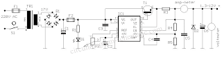
This circuit is a circuit diagram of a variable power supply. Variable power supply circuit is a simple but reliable one based on an integrated voltage regulator from the eldest LM723. R2 set the output voltage. The maximum flow is determined by the value of R3, the excessive current in the circuit protection senses R3 and LM723 voltage output stage begins to close off this fast voltage approaches 0.65 V. In this way the current through R3 can never exceed 0.65/R3, even if output is shorted. C3 and C4, both ceramic, should be placed as close as possible to the integrated circuit, because the LM723 can be vulnerable to unwanted oscillations. The following is a schematic drawing:
Source: www.zen22142.zen.co.uk
This circuit is a circuit diagram of a variable power supply. Variable power supply circuit is a simple but reliable one based on an integrated voltage regulator from the eldest LM723. R2 set the output voltage. The maximum flow is determined by the value of R3, the excessive current in the circuit protection senses R3 and LM723 voltage output stage begins to close off this fast voltage approaches 0.65 V. In this way the current through R3 can never exceed 0.65/R3, even if output is shorted. C3 and C4, both ceramic, should be placed as close as possible to the integrated circuit, because the LM723 can be vulnerable to unwanted oscillations. The following is a schematic drawing:

The LM723 works with the input DC voltage V and IC 9,5-40 itself can be the source of about 150 mA if the output voltage is not more than 6-7 V below the input. When the external pass transistor is used (in the usual emitter-follower mode), the base-emitter of T1 is a significant resistance and the output stage of integrated circuits is relatively light load. All the current drawn by the load through a T1 and it decreases the amount of power that is proportional to the current and the difference between input and output DC voltage.
Source: www.zen22142.zen.co.uk
adjustable regulated power supply - 1.2 - 15Volt /3A
adjustable regulated power supply 1.2 - 15Volt /3A
This kit provides a variable output power supply ranging from 1.2 to 15 Volt / 3 A. It uses Low Dropout Positive Regulator LM1084 in TO220 package for delivering variable output voltage.
Schematic
 Input - 18 VAC/DC
Output - variable output from 1.2 ~ 15 VOLT / 3 A Regulated low ripple DC voltage
Heatsink for regulator IC
On board bridge rectifier to convert AC to DC
LED indication at input of IC
Power Battery Terminal (PBT) for easy input and output connection
Zener trimmed band gap reference, current limiting and thermal shutdown (provided by IC feature)
Filter capacitors for low ripple DC output
Onboard PCB mounted Potentiometer (POT) for varying the output voltage
PCB dimensions 46 mm x 58 mm
Four mounting holes of 3.2 mm each
Parts List :
BR1 = BR34
CN1 = 2 PIN PBT
CN2 = 2 PIN PBT
C1 = 2200UF /25V
C2 = 0.1UF
C3 = 47UF / 25V
D1 = RED LED
P1 = 4.7K POT
R1 = 1.5K
R2 = 120ohm
U1 = LM1084
This kit provides a variable output power supply ranging from 1.2 to 15 Volt / 3 A. It uses Low Dropout Positive Regulator LM1084 in TO220 package for delivering variable output voltage.
Schematic

Output - variable output from 1.2 ~ 15 VOLT / 3 A Regulated low ripple DC voltage
Heatsink for regulator IC
On board bridge rectifier to convert AC to DC
LED indication at input of IC
Power Battery Terminal (PBT) for easy input and output connection
Zener trimmed band gap reference, current limiting and thermal shutdown (provided by IC feature)
Filter capacitors for low ripple DC output
Onboard PCB mounted Potentiometer (POT) for varying the output voltage
PCB dimensions 46 mm x 58 mm
Four mounting holes of 3.2 mm each
Parts List :
BR1 = BR34
CN1 = 2 PIN PBT
CN2 = 2 PIN PBT
C1 = 2200UF /25V
C2 = 0.1UF
C3 = 47UF / 25V
D1 = RED LED
P1 = 4.7K POT
R1 = 1.5K
R2 = 120ohm
U1 = LM1084
Adjustable power supply using LM317
Adjustable power supply using LM317
 For the LM317:
R2 = (192 x Vout) - 240, where R2 in ohms, Vout is in volts and must be at between 1.2 V and 35 V.
Vin should be at least 2.5V greater than Vout. Select a wall adapter with a voltage at least 2.5 V greater than your regulated output at full load
Maximum output current is 1 A. Use proper heatsink for LM317 if it has to dissipate more than 1W.
The tab of the LM317 is connected to the center pin.

R2 = (192 x Vout) - 240, where R2 in ohms, Vout is in volts and must be at between 1.2 V and 35 V.
Vin should be at least 2.5V greater than Vout. Select a wall adapter with a voltage at least 2.5 V greater than your regulated output at full load
Maximum output current is 1 A. Use proper heatsink for LM317 if it has to dissipate more than 1W.
The tab of the LM317 is connected to the center pin.
Subscribe to:
Posts (Atom)